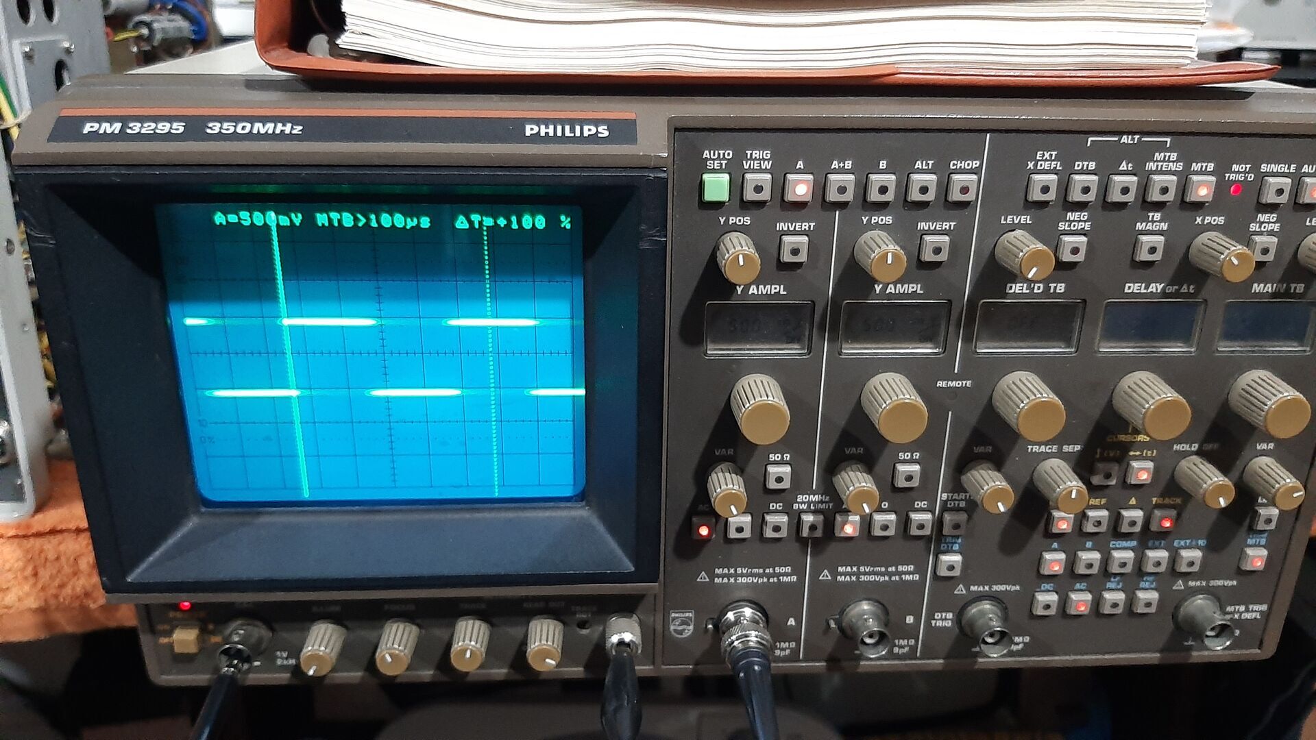
Repairing a Philips PM3295 Oscilloscope
The previous owner threw in the towel. I will take on the challenge! A new series…
2025-05-31

- English video episode 1 on Odysee
- English video episode 2 on Odysee
- Dutch video aflevering 1 on Odysee
- Dutch video aflevering 2 on Odysee
Documentation
A viewer also repaired a PM3295 and he succeeded
David Boal from Spain had a similar problem and he was so kind to share his repair with us:
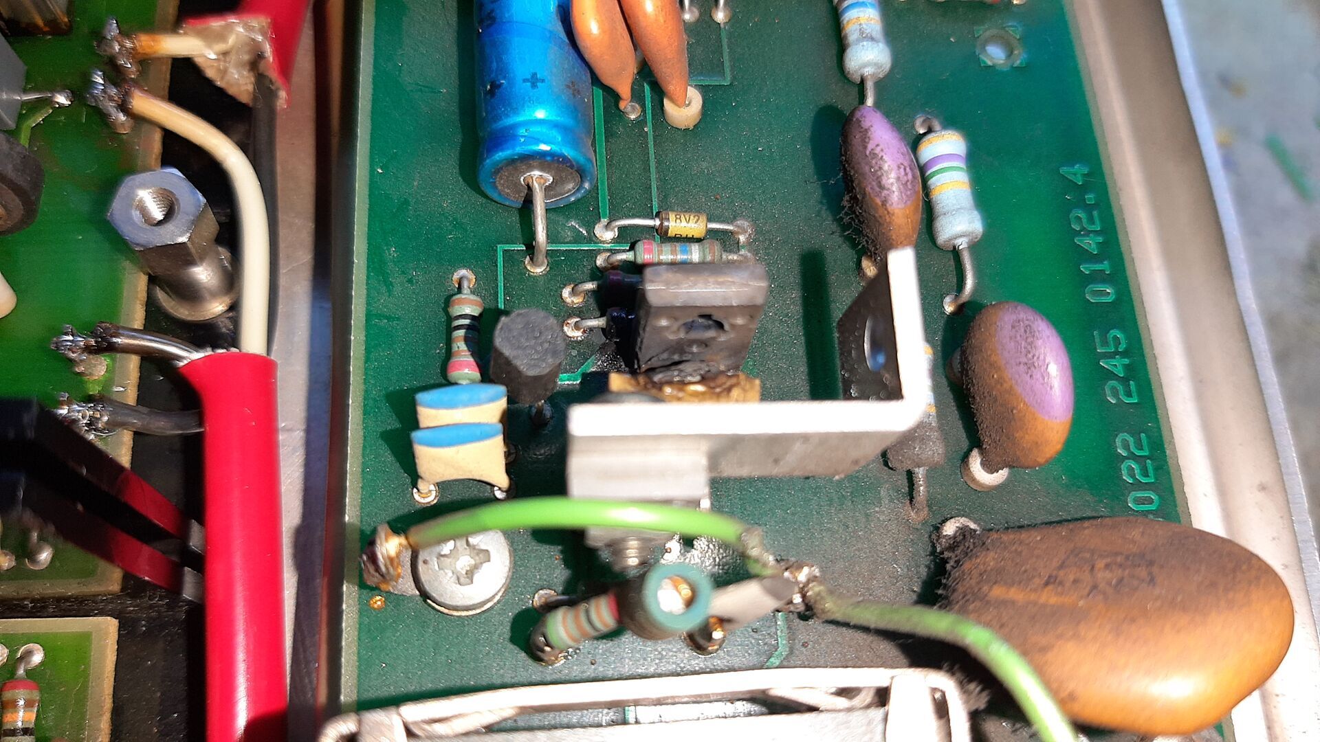
He wrote: I’ve seen your videos on repairing the Philips PM3295 oscilloscope. I have one like this, and I replaced the two RIFA capacitors in the primary converters that had disintegrated and which I changed about two years ago. Everything was going well until a month ago, when the screen went dark, showing no trace or text, and it started to smell of burnt electronic components; a jet of smoke came out the back, where the fan is located.
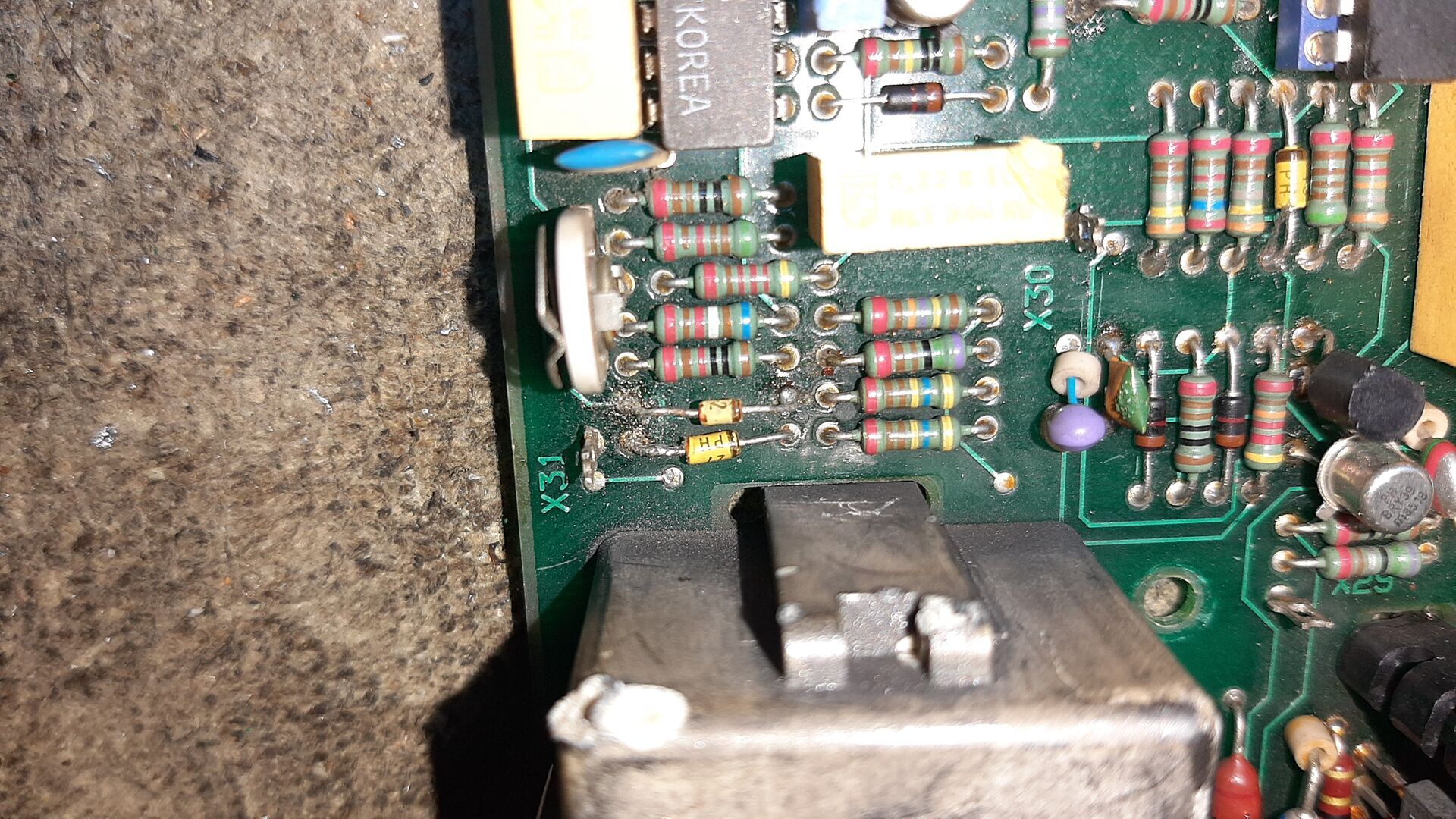
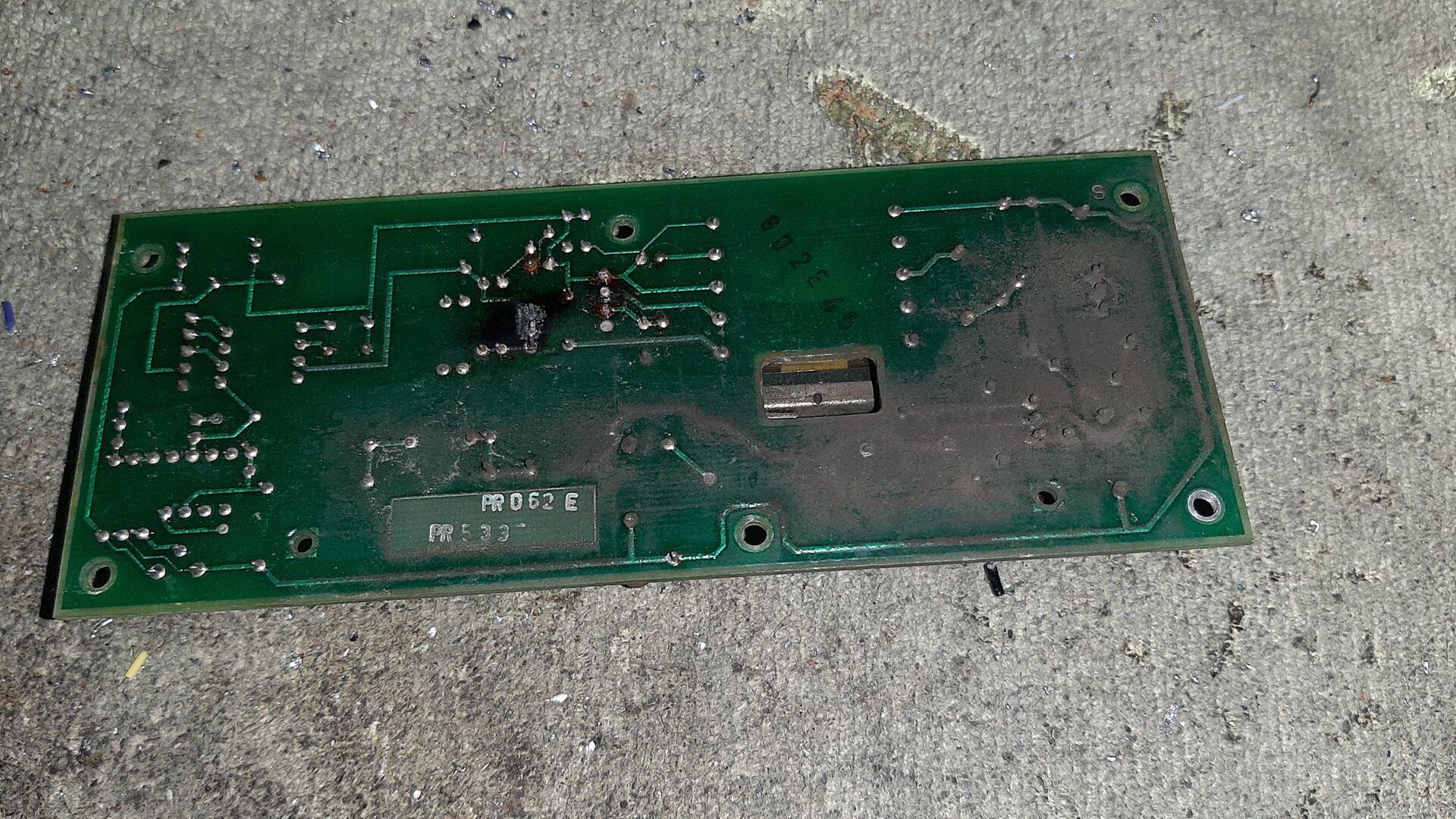
I disassembled the power supply and saw a melted 100nF/100V polyester capacitor and the BD248 transistor, next to said capacitor, destroyed, which charred the fiberglass of the printed circuit board. A 1 ohm, 1/4W, 1% tolerance resistor on the +50V input was shorted; the BDX36 and BF422 transistors were leaking; the BZV11 precision zener diode, cut, which I replaced for testing with another normal 6V2 zener with a 5% tolerance, in the high-voltage converter.
In the secondary converter, I also found the BZV12 precision zener diode cut, replaced for testing with another 6V2 zener with a 5% tolerance as well.
I carefully cleaned the two printed circuit boards above and below of the blackish dust with compressed air, first with a paintbrush and isopropyl alcohol and compressed air afterwards, as well as the chassis, under the printed circuit boards in the same way.
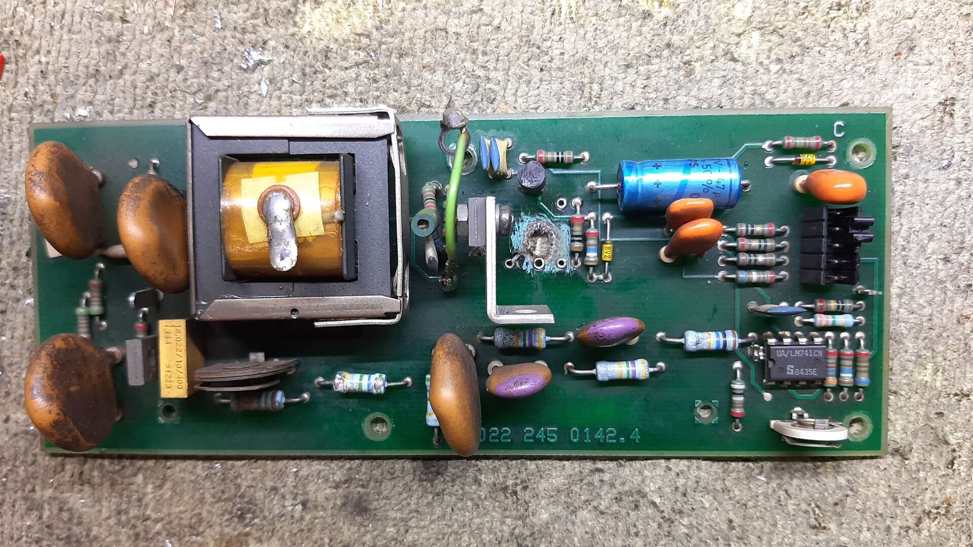
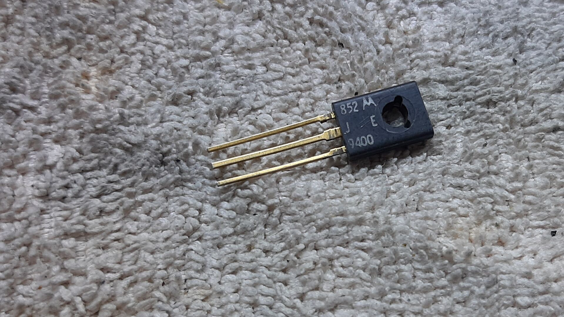
But now, I have no trigger, the LED labeled “NOT TRIGG’D” is on. I already have a trace and text on the screen, but the BDX36 has been replaced for testing by a Motorola MJE9400, because I mounted a BDX37 bought here at EA, which is fake, it must be a copy. I suspected, since nothing was showing on the screen, that the high-voltage multiplier to obtain the +21kV might be faulty, but I didn’t throw in the towel, so I tried using the MJE9400 instead of the BDX36. I was very pleased to see that with the transistor in question mounted instead of the BDX36, the oscilloscope screen “came back to life,” because everything else worked.
I’m now having the trigger problem and suspect that the LM324N and LM339N integrated circuits, respectively, may have failed, although I’ll check “Line 2” first, in case the problem lay there. On the other hand, the text unit was optional, as was the IEEE interface, which my PM3295 doesn’t have installed.